
Half the diameter.
Twice the capacity.
How siphonic drainage works, the hydraulic logic behind it, and the materials and standards it is built to. The whole system, from the diagram to its counterpart on site.
Multiple Geberit Pluvia roof outlets connect through a zero-slope collector pipe to a single vertical stack — the basic unit of the siphonic system. On large roofs several groups are installed; each group has its own stack.
Roof outlet — Geberit Pluvia outlet
The Pluvia roof outlet draws water from the roof surface without admitting air; the function disc and anti-vortex baffle work together. Unless air ingress is prevented, the system cannot hold a vacuum and priming will not begin.
Collector pipe — zero slope
A horizontal HDPE line that carries the flow of multiple roof outlets and runs beneath the beams. Because the slope is zero, it does not interfere with the building's architecture; every joint is made by butt welding to DVS 2207.
Vertical stack — the vacuum driver
A vertical HDPE line positioned at every other column. The falling water column places the collector pipe under vacuum (typically −0.45 bar, peak ≤ −0.78 bar). The system primes and transitions to full-bore flow.
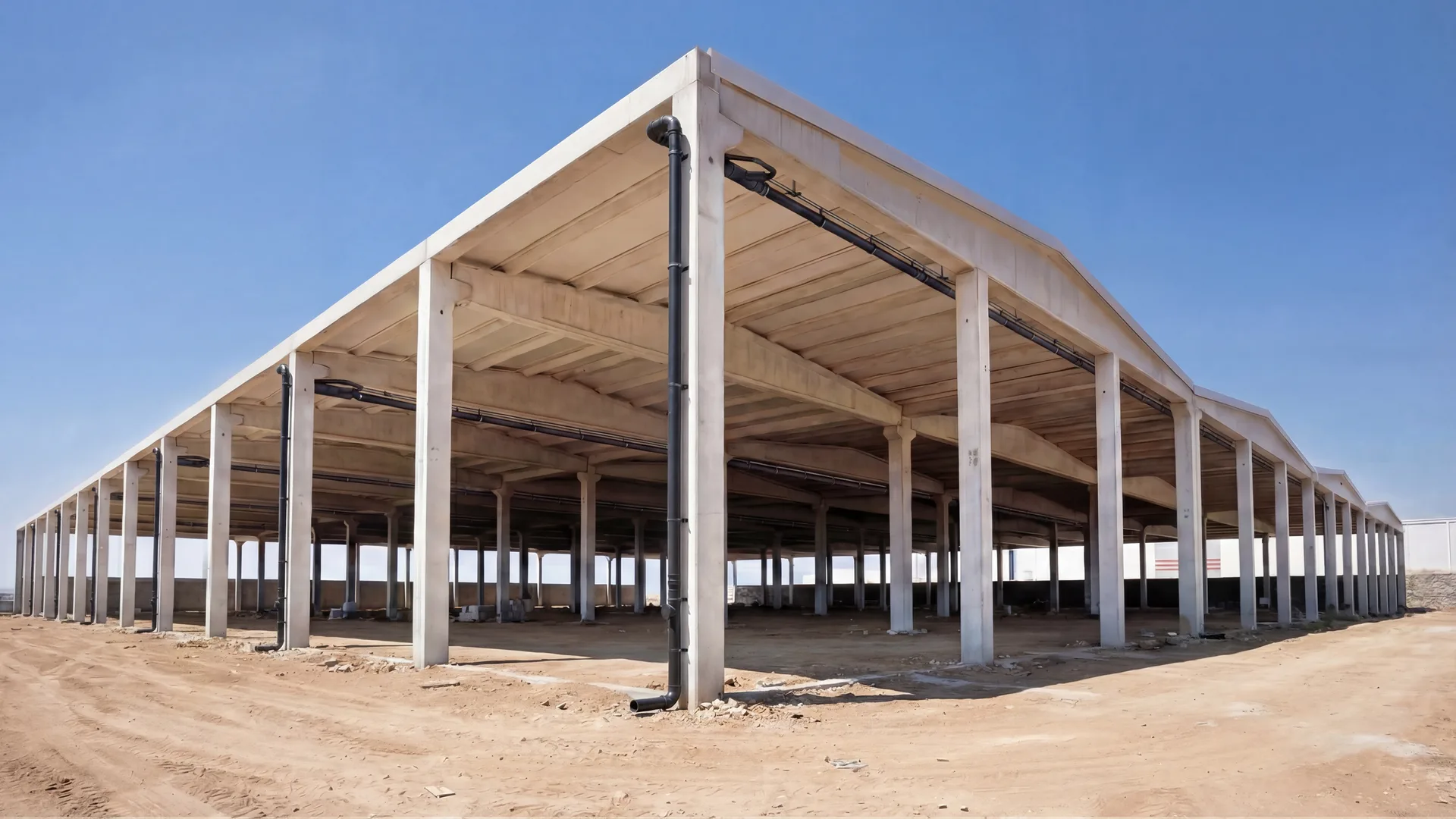
The diagram above is the technical counterpart of exactly this scene — a zero-slope horizontal HDPE collector pipe feeds the vertical stacks that connect to selected columns via elbows.
Not gravity —
pressure does the work.
Thanks to the air barrier (anti-vortex) placed at the roof outlet, siphonic drainage fills the pipe completely with water from the point of entry. The negative pressure generated inside the pipe draws water from the collector pipe toward the stack, evacuating it horizontally.
- Phase01
The air is swept out
As rainfall intensifies, the anti-vortex baffle of the Geberit Pluvia roof outlet keeps air from entering; the air within the line is swept from the collector pipe toward the stack.
- Phase02
Full-bore flow
The pipe cross-section fills 100% with water. No air pocket remains. This is the single condition that makes the siphon possible — TS EN 12056-3 §4.1.
- Phase03
Negative pressure builds
The water column falling through the stack creates negative pressure in the system. Pressure in the horizontal line drops below atmospheric; the system begins to draw water off the roof.
- Phase04
The line reaches equilibrium
A Bernoulli energy balance is established: the height difference fully offsets the friction losses (HL) along the line. Flow stays stable at 4–6 m/s, carrying several times the flow rate of a gravity system.
A line
signed off to standard.
Every system is delivered to international standards, with a BIM calculation and certified welding procedures. The specifications below are the technical index of a typical industrial installation package from Ahmet Bilgin Yapı Malzemeleri.
| Standard | TS EN 12056-3 |
|---|---|
| Pipe Material | Geberit HDPE (high-density polyethylene) |
| Pipe Diameters | ø 40 — ø 315 mm (DN 50/56/75/90/110/125/160/200/250/315) |
| Jointing | Butt welding, electrofusion (DVS 2207-1 / DVS 2207-15 certified) |
| Roof Outlet | Geberit Pluvia · function disc / anti-vortex · 14 / 25 / 45 / 60 / 100 L/s models |
| Hydraulic Calculation | Geberit ProPlanner — Revit BIM plug-in (Bernoulli + Darcy-Weisbach) |
| Operating Vacuum | Typical −0.30 / −0.45 bar · peak ≤ −0.78 bar (TS EN 12056-3 limit) |
| Flow Velocity | 4 — 6 m/s full-bore flow |
| Degree of Filling | ψ = 1.0 (after priming) |
| Support System | Galvanized steel clamps, 0.8 m for ø50-90 · 1.1 m for ø110 · 1.2 m for ø125 |
| Operating Temperature | −40 °C → +60 °C |
| Service Life | ≥ 50 years (Geberit HDPE) |
| Fire Class | B-s1, d0 (with flame-retardant variant) |
| Warranty | 2-year Bilgin workmanship + Geberit HDPE manufacturer system warranty |
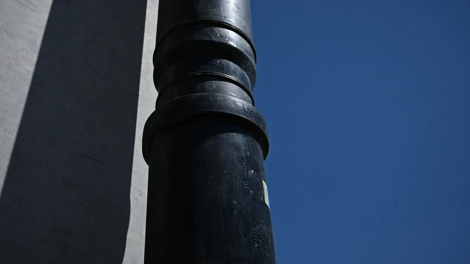
From bare plot to first
downpour.
The timeline of a single Bilgin project: from bare ground to building enclosure, through to how the system engages in the first rainfall. At every stage, engineer supervision and step-by-step documentation are applied.
 01
01Bare ground, blue sky. Not a single line yet — but the roof plan, rainfall data, and collector pipe route are already taking shape on the ProPlanner screen.
 02
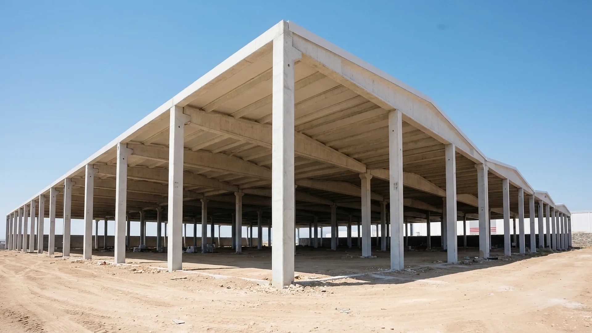
02Concrete columns and beams take their places. Bilgin is engaged at this stage: the stacks are positioned according to the column layout, and the bracket plan for the under-beam runs is finalized.
03The frame is complete and certified welders begin placing the siphonic lines. A vertical HDPE stack at every other column — the horizontal collector pipe above directs the water it gathers from multiple Pluvia roof outlets to this point.
 04
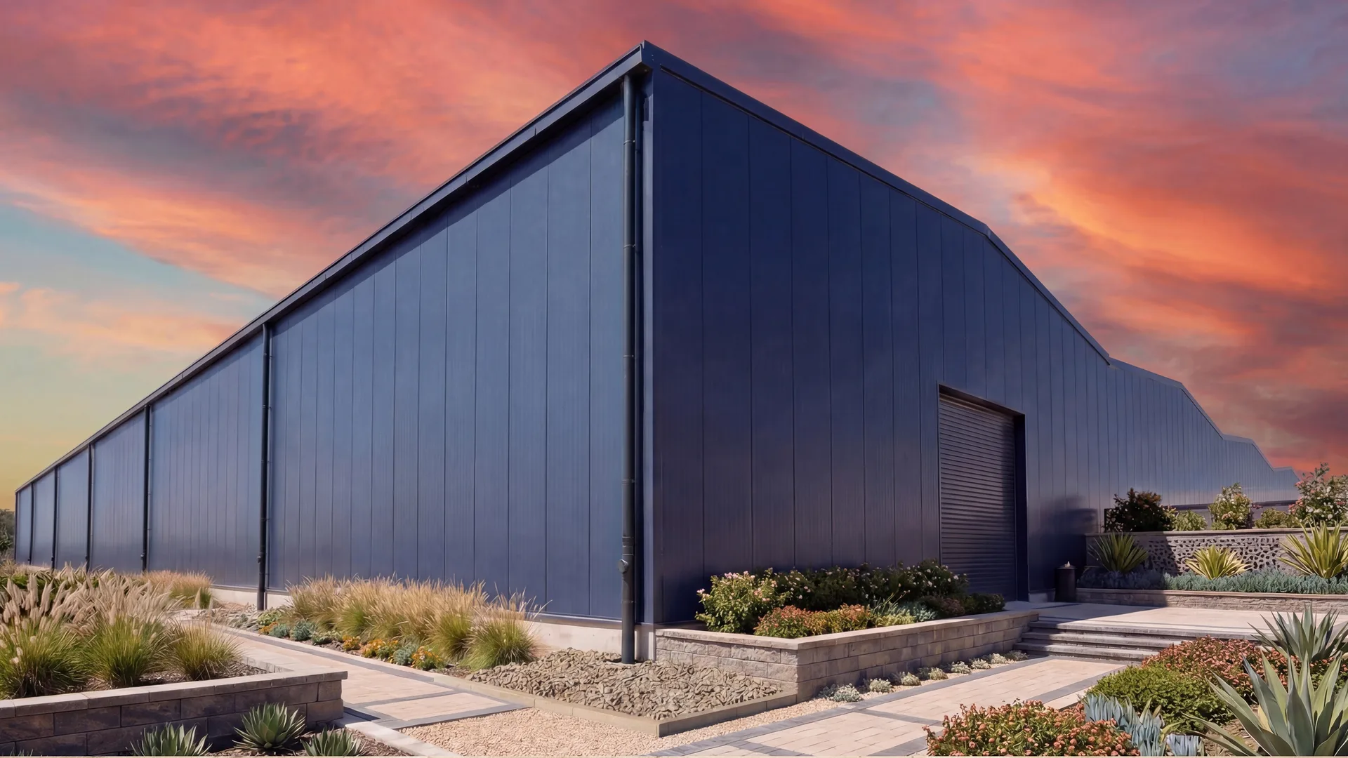
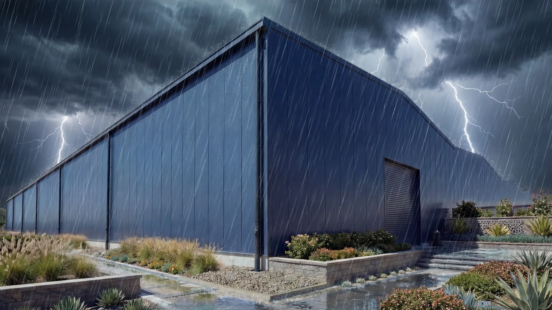
04The blue sandwich-panel façade is closed up. A system that is unseen but ready: Pluvia roof outlets on the roof, vertical stacks beside the columns, collection at ground level. The building enters its first evening.
 05
05Rainfall intensity crosses the threshold. The anti-vortex baffle disc prevents an air pocket; the water column falling through the stack creates negative pressure in the system. Within seconds full-bore flow begins — water never pools on the roof.
Share your roof plan and let our engineer produce the hydraulic calculation.
Start a Project